 |
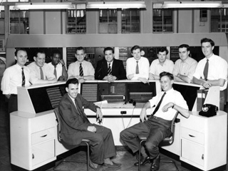
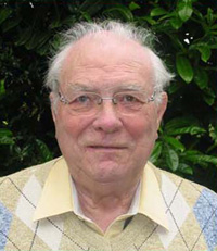
John Burt tells us about his work for the GPO between the years of 1942 to 1966, which included a lot of time in Faraday Building... |
My first posting to Faraday was Christmas 1942, when I spent three months as a Y2YC on construction duties, mainly installing a PBX for the Repeater Stations speaker circuits.
In those wartime days it seemed to me a very busy place; there were Military Policemen on all doors, so one could not get into the building without a passcard.
There were telephone operators everywhere, as the Trunk Service was mainly manual. A limited 2VF dialling system was in use to and from Birmingham / Manchester. I do not remember the number of Switchrooms; there was certainly 6S in the South Block. Toll A had recently gone auto in the South East Block, but Toll B was still manual. In the North Block there were at least four large switchrooms.
The 3rd floor Repeater Station was mainly an audio station except that the first British coaxial system, Birmingham to Manchester was installed, (more later). I left in about March 1943, was made up to USW and spent the rest of my time till call up in 1945, on auto duties at Waterloo Exchange.
1950-1959
After serving as a Sergeant in the Royal Signals in Palestine, I returned to auto duties in Bermondsey exchange. In 1950 an opportunity arose to transfer to Faraday on transmission duties. I was then put on maintenance of the original Birmingham 'A' Coaxial system mentioned earlier.
This system was designed by the old Wireless Branch of the then Engineer in Chief's Office, so it had a number of different design features. All the filters were crystal filters, but the channel spacing was five kilohertz and not four. There were therefore only 8 channels per group, and not 12. There were 5 groups to a supergroup, so we had 40 chans to a supergroup and not 60.
The cable itself was of 0.45 inch. and the inner was separated from the outer by a spiral of cutopa tape. This led to problems some years later when doing high voltage testing, the inner conductor became welded to the outer, due to the cutopa string allowing the inner conductor to sag. When the .375 cables came into use they had solid spacers to avoid this problem.
This Birmingham 'A' system had 4 supergoups with this sub-standard spacing, and then the 'Lines Branch' took over all subsequent design work. As a result, standards changed re, frequency spacing etc, and 12 channels per group was introduced. As a result the 'A' system had no supergroup 5, just 1,2,3,4 & 6,7,8. Some went on to Manchester, and one on to Newcastle.
It was a very interesting experience to have worked on it. The Audio & Co-Ax staff were then integrated in L3F in about 1952/53.
In those days we had many long distance audio circuits, all on loaded cables ie 88 millihenries every 2000 yards. Often loading pots were removed by the local jointers for a variety of reasons, which led to problems of frequency response. It was not considered wise to have voice telegraph circuits on carrier systems, for reasons of possible carrier system frequency instability. Some of the circuits went as far as Edinburgh & Glasgow, taking many hours to locate faults.
I personally can well recall tracing a fault on the Air Traffic Control circuit from London Airport to Shannon in Ireland. This was audio all the way, and the technician in Ireland said that he could not repair the fault till the bus came, as he had no matches to light the gas stove to heat his soldering iron! Faults on audio circuits needed a technique of their own in those days, all now gone and forgotten.
The Speaking Clock
In the 1950s there were two clocks (perhaps there are still). One in Holborn exchange, and one in Liverpool. They were connected by two audio omnibus circuits passing through many major towns. So, on one circuit the London Clock was fed to all stations, and on the return half the Liverpool Clock was fed to the same stations. So, on the failure of any one clock or circuit the other could take over.
Coronation Day
1953 was the year of the Queen's Coronation; all the staff on duty were called to the Exec Engineer's office; a much revered Jim Isherwood who instructed us that we were to do no work at all unless it was to do with any of the circuits that had been set up in connection with the Coronation.We were to bring plenty to eat, drink and read, and not to touch any equipment. This might seem to be a strange instruction, but bear in mind that in those days quite a lot of failures were due to 'Engineering Working Faults'. Needless to say the day went off very smoothly.
I left the L/3F Repeater Station on promotion to Assistant Engineer in 1956, but in those 6 years I had received a thorough grounding in line transmission, which stood me in very good stead for the rest of my career.
Faraday Building - Assistant Engineer Duties
In the 1950s the Area Engineer I/C Transmission, Trunk Test, and Internal Development duties, was a Robert Holliday, known as Uncle Bob, or 'The Hat', due to him wearing his Homburg hat nearly all the time. He had a tendency to bully his staff, especially those who would not defend themselves. After serving the customary 9 months in Circuit Provision Control (CPC), I was called into see Uncle Bob, and told that I was going to Trunk Test, but not having worked there, I was going to have 4 weeks training on all aspects of the work, and was to keep a notebook for his inspection; you see what I mean about Uncle Bob?
(As a matter of interest, I kept this book up to date for the rest of my career, and it is now with another in the BT Archive Collection.)
I became one of the Rota Duty Engineers, responsible for the functioning of all aspects of Faraday for 24 hours. You must bear in mind that not only the London Trunk network passed through Faraday, but many Government private circuits, and also BBC and Independent broadcast circuits.
Uncle Bob, that is Mr Robert Holliday, our Area Engineer, was, in spite of all his faults, very loyal to his staff. One evening when on duty I received a call from the City Police, who were holding one of our staff on suspicion of having stolen property from him, and would I go to the Police Station to identify it so that the man could be charged. One realized that one should do no such thing without advising Uncle Bob first.
After advising him of the situation, I was told that I should go, and whatever the man had taken, I was to say that it had no value and that the Post Office would not press any charges. At the Police Station I was shown a reel of multicore solder that the man had taken; this was obviously of some value, and the Police were somewhat put out when I said that it was surplus to requirements and had no value. The man was released, but had to face the wrath of Uncle Bob the following morning.
The Transatlantic Test Room Kingsway
The first Transatlantic telephone cable had been laid in 1956, and had transformed the quality of communication between the two continents. I felt quite honoured to be transferred to duties there in July 1959. Although the terminal was in London Kingsway, which was in a deep level tunnel under High Holborn, the terminal, together with the Kingsway auto exchange and repeater station, was staffed by Long Distance men, who also staffed Faraday Building.
The TAT 1 cable ran from Oban in Scotland to Clarenville in Newfoundland. This section was the original American design, having two cables, one for each direction of transmission. This section carried 36, 4kHz circuits on three 12 channel carrier groups.
From Clarenville to Sydney Mines in Nova Scotia the system was a Post Office designed single cable of greater bandwidth, having directional filters in the repeaters to separate the two different directions of transmission. This cable carried 5 groups of 12 channels in each direction. Only three groups were used for the TAT cable system. From here the circuits reached their destination over the domestic systems. For the US circuits this was White Plains, just north of New York, and for the Canadians, Montreal.
The Start of Something Big
At the time, I do not think that all of us realised that we were involved in the 'Birth of true International Communications'.
The demand and growth of traffic for these high quality circuits was fantastic. There were a few circuits allocated to the Continental countries, say one each to the Scandinavian countries, the Netherlands etc.
On top of this the Telegraph Companies, whose submarine cables took only one or two slow signalling circuits at the most, clamoured for an audio channel that would take up to 24 telegraph circuits.
In these early days of the late 1950s other cables were being planned, and TAT 2 from the USA to France was soon to come into service and bring relief. One interim measure was to introduce 2 kHz working on calls from the London area to customers in the local area of New York during the peak period of the day.
This equipment was designed by the Telephone Manufacturing Company (TMC), who managed to squeeze two audio channels of about 1900 Hz in the space of a normal 4 kHz channel. These equipments could be switched from one mode to the other quite swiftly.
Radio Broadcasts to and from America increased tremendously, and for news reports, a normal speech circuit was allocated ( Lon - WP 42 or 44 often being used I remember). These were always set up and monitored by the staff at TAT Test Room.
There was 'Music in Band' equipment which took the space of 2 channels for a 6.4 kHz circuit, or 3 channels for a 10 kHz circuit. These were only used for higher quality use as bandwidth was very expensive to hire in those days.
The Next Change
The next great change was certainly a joint US/UK project. TMC had developed a 16 channel carrier system that was compatible with the normal 12 channel system. There was a slight problem of interference from the pilot signals on the ordinary system, but these were soon overcome. The 16 channel system had a 3 kHz spacing instead of the usual 4 kHz, but due to the design of the channel filters, very little audio bandwidth was lost. This was, I seem to remember, from 250 - 3150Hz. (All my notes are now with the BT Archives). These 16 channel Channel Groups enabled the TAT 1 cable to carry 48 channels instead of the original 36.
The USA part of the project was to design a computer system known as TASI; that is Time Assignment Speech Interpolation.
In those days, one transmission path was used for speech, from London to White Plains (New York), and another for speech from White Plains (New York) to London. Hence the use of two submarine cables.
In this TASI system, in theory, 36 channels could be connected to the computer equipment, although initially, until the introduction of the CANTAT cable, only about 24 were used.
In point of fact, in any conversation, usually only one person speaks at any one time, therefore the other persons transmission path can be given to anyone else who is speaking in the other direction. In this case, the pool of channels can be in use for all of the time, and the increase factor is over 2.5 times. So when a person speaks, within 5 milliseconds a speech detector will operate and inform the common equipment that a talker requires a channel; it will select and signal over the channel to the equipment at the other end, the number of the caller's 'Talk' circuit and then connect the two talkers together, with no noticeable 'clipping' of the speech.
This system was most successful and was in use on most of the early cables. (I believe that a similar, but much more sophisticated system is in use today).
During the period that I was in TAT Test, the equipment and staff moved up to the North Block of Faraday Building, next to the Continental Centre (IMC/C), with the Transatlantic Test being now known as IMC/A.
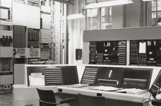 |
View of Test Room: |
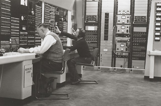 |
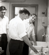
Len Tytherleigh (Tiger), and Dave James working on the Test Desk. HF switching rack in background. |
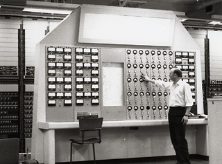 |
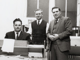
Frank Norris by the HF control panel, where all incoming carrier group pilots were monitored. |
The move to Faraday took place in 1962, and between this time, and the time that I left on promotion in 1966, a vast growth of the International network was taking place.
CANTAT 1 came into being; a single cable of Post Office design, which had five groups of 16 channels, and ran from Oban to Hamden in Newfoundland; a cable also ran from Gairloch in Scotland to Iceland (Scotice) and then on to Greenland and Canada. This cable was known as Icecan. These cables were also used for the North Atlantic Air Traffic Control circuits.
TAT 3 was commissioned using an American system based on the Post Office 'one cable' design. This went from Widemouth in Cornwall to Tuckerton on the US Eastern coast. This was even a larger system.
The COMPAC cable was laid across the Pacific from Vancouver to the Hawaiian Islands on to Fiji, Aukland, to Sydney, Australia.
The south east Asian cable came into use from Cairns in Australia, via Guam, to Hong Kong. London had connections via the American Trans Pacific cable. Development was happening all the time. Most if not all of these cables were equipped with the TMC 16 channel carrier terminals. The Post Office provided staff from Telecom HQ to act for the local companies in overseeing the installation of the equipment.
Television Broadcasting
Whilst reasonable quality audio channels were available for radio companies, it was not possible to transmit television over these cables due to bandwidth limitation.
The BBC Research came up with a very clever solution, and that was to compress the bandwidth required, so that pictures could be sent over a 10 kHz 'Music in Band' channel. This was done by discarding one of the interlaced vision frames, and then sending every other line of picture. Other measures were taken to reduce the bandwidth required. The resultant signal was then sent over the circuit at a very slow rate. For example a three minute shot took nearly an hour to transmit.The resultant quality was very poor, but considered sufficient when recording important events, for example, these were the days of the Gemini space shots, and take offs and landings were great news. (More later on Space coverage by IMC/A).
The next great leap into the future came with satellite communications. Experiments in the US with the ECHO satellite proved very successful. ECHO was in fact a large inert reflective 'ball', which rotated the Earth in a low orbit. Using two stations The US bounced radio signals bothway from the West Coast of America to the East Coast. These tests were successful, so on 11th July 1962, an active Orbital satellite was.launched - TELSTAR. Using two bands of frequencies, signals were transmitted to it, where the frequencies were changed to avoid interference with the incoming signals. As the satellite was in a low orbit of a few hundred miles, the time that it was in view from both England and America was very short indeed, i.e. about 20 minutes.
It did indeed amaze the World, and proved the feasibility of satellite communication. They even wrote a song (TELSTAR) about it, which is still played today on occasions.
The big problem of this type of system is that to ensure constant communication between the two earth stations, a series of orbiting satellites would be needed, at least 80. Also at least two aerials would be required each site.
The great writer/scientist Arthur C Clarke had, many years before, spoken of a geostationary satellite (approx 23,000) miles in space remaining stationary relative to a defined point on the Earth's surface. In this case only one satellite would be needed to serve one area/region.
The problem at that time was however, would be the delay in speech propagation (in the order of 1.5 seconds each way) be acceptable to the user? In no way could one go to the expense of launching one (at the cost of millions) just to find out, so some other way had to be found.
Staff
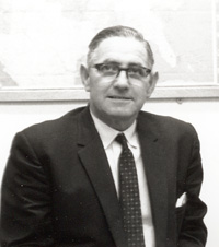
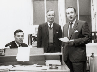
Before I go on to describe Early Bird, I thought it about time that I introduced some of the staff.
The Great Experiment
In the early 1960s calls between London and New York were connected on a manual basis, that is the subscriber (now called a customer!) dialled INT and quested a call. Early on, this was connected on a delay basis, with the operator calling the customer back when there was a line available. Later on as more lines became available, "Demand' working was normal. On connecting the call the UK operator selected a free circuit and rang on the line with a 1000/20 Hz signal. The US operator would then accept the number required and connect.
Knowing this, one can now understand how the tests were conducted. The tests were arranged by the PO Research/THQ Development groups for the London to White Plains circuits, and by the Bell Telephone Laboratories in the US for the White Plains to London circuits. A number of circuits that did not go through the TASI system were utilised for the purpose of these tests; they were connected through tape recorders that introduced a precise amount of delay.
The delay varied from about 0.5 seconds in one case, and through 0.5 second steps up to about 3 seconds. (I am not quite certain about the actual delays involved). The delay was in both directions, thus giving the effect of a call over a satellite connection.
Customers were selected at random, and connected to a specific circuit according to a schedule produced by the test organisers. At no time were the calls monitored. After the call was over, the customers were asked their opinion regarding the quality of the call. This varied from acceptable to that of severe dissatisfaction (this happened if the circuit had been one of long delay time).
After many weeks of tests, it was concluded that a call routed over one satellite having a propagation time in the order of 1.5 to 2 seconds would be acceptable, whereas a routing over two satellite connections would not be. (In point of fact, in a number of cases, it is sometimes only possible to make connections via two satellites).
Rota Duties
Needless to say the importance of the International Service warranted 24 hour attendance on the part of the staff. I think it is true to say that such was the reliability of the cable amplifiers, we never had a failure due to equipment on the cable system itself.
We did however, have many failures due to trawlers cutting the cables with their fishing equipment. The fishermen were offered financial compensation if they sacrificed their trawl, but this was not a sufficient inducement for them to cut their gear and save damaging the cable.
So in the early days when there was only the TAT 1 cable, the loss of one cable direction was very serious, and the only thing that could be done was to bring up as many radio channels as possible. These were connected to the failed direction of transmission, the other direction was left on the good half of the cable that was usually working.
Once the French TAT cable came into use, a form of 'Mutual Aid' came into being. Depending on the cable failure, French or ours, a number of important circuits would be diverted from one country to the other to be made good on the others cable.
Needless to say the circuits to be diverted had already been scheduled by the Headquarters staffs of the three countries concerned. With the advent of CANTAT, TAT 3, etc, the 'make good' schedules became quite involved. I personally experienced a cable failure on TAT 1, during one night with the failure of CANTAT the next night! Probably the same fishing fleet.
The Rota AEEs did a different set of duties to the Technical Officers, so when coming on duty one was not certain of who would be on duty with you. Sometimes there were a very few couples of TOs who might give some concern. However there were two who must surely be mentioned:
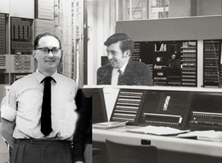 |
Master Chefs, Morrie Gladwell and Ron Calfe |
It must have been about 1964 or 1965, when the space age for telecoms began. After the tests for the acceptance of a slight delay in telephone calls, up went HS303, more popularly known as Early Bird.
The signals were transmitted from Andover in the East of the USA, and were in three groups, one for the UK, one for France and the third for Germany.
Each of the European countries had their own Earth Stations. In the UK we had Goonhilly Downs, France had Plemeur Bodou, and there was Raisting for the Germans.
To gain experience, each of the above stations would receive all the signals on a week, and week about. For example, week 1, Goonhilly would receive the signals, which would be sent up to London IMC, and there the French group would be sent on to France, and likewise the German group of circuits would be sent on to Germany. The following week the signals would be received by Plemeur Bodou, and then sent back to the other countries, Finally the third week the signals would be received at Raisting in Germany.
As a matter of interest, Goonhilly has always had a Dish Aerial for receiving and transmitting signals; this has now become the standard for all countries.
Initially the US, and possibly some other countries, used a Horn Aerial within a large plastic dome. The problem with this method was that during, heavy rain , the signals from space, (already very weak), were greatly attenuated, giving a high level of noise if not cut out altogether.
This experiment proved very successful, and thus other satellites went up and we were in the modern era.
Also about this time the Americans were conducting the Gemini Space Hops.
Gemini Space Hops
As a preparation for the 'moon shots', two men were sent up in a capsule; initially just up into the outer stratosphere and down again, where they landed into the Atlantic Ocean, and were picked up by the US Navy.
All aspects of the final methods used on the 'moon shots', were being thoroughly tested. The tests ended with an orbit of the Earth, then the 'moon shots' began.
The London IMC/A was very involved in the communications for these shots. The frequencies used for the radio signals were very short, and a direct line of sight to the space capsules was required from the US. Due to the rotation of the Earth, 'the US could not have direct communication throughout the 24 hours, so other radio stations were set up around the world, eg the Canary Islands, and elsewhere. These signals were sent back to Cape Canaveral etc via the Transatlantic cables. IMC/A were required to monitor these circuits constantly, and to make good in the case of any failure.
This requirement was a long term responsibility', and all of the 'moon shots' were also monitored.
Also in the early 1960s semi - automatic signalling was introduced, where the controlling operators in London & New York could dial direct into the other country. Before this came into full use, the engineers at each end made a series of tests by dialling into the other country.
Calls were made to the main Test Desks, and the response from the local man in (say) Oklahoma was one of amazement that London England could actually dial into the States. On more that one occasion I was asked if London, England was part of the Bell System.
I did however, as a matter of fun, on one occasion, call London, Ontario. It shook him when he found himself talking to the 'real London'.
It was between 1962 and 1966 that the semi - automatic service really expanded; the operators were soon dialling direct to Australia, New Zealand, Hong Kong, and Tokyo.
The dialling system used was a combination of two frequencies; one for the seizure of the distant Register, and the other giving the 'Proceed to Send' signal to the outgoing Register. The signals were then sent as a series of multi - frequency signals, similar to those today in the National Network. (This system was AC10 MF 1).
The system was very versatile. For example, if the London Register found that all the direct circuits to Sydney were busy, it would then select a Montreal circuit, and send all the routing information onto the Montreal Register, which would then search for a free Montreal - Sydney circuit. If all these were busy, this routing information was then sent on to Vancouver, which would then search for a free Vancouver - Sydney circuit. If none were found, it was only then that a busy signal would be returned.
This does sound a lengthy process, but was in fact done in a matter of a very few seconds.
One night, Headquarters instructed us to check the transmission levels on all combinations of this circuit routing. As you can imagine with the numbers of line involved it took most of the night.
To control the task we had engineers from all countries on the same omnibus circuit; you can just imagine the humour that was being exchanged. The camaraderie that exists between telephone engineers in different countries has to be experienced to be believed.
In particular we got on extremely well with our American colleagues; our technical jargon was different, and we found ourselves using a combination of both countries between us.
For example, I well remember the occasion when there was a fault on an American government line in the Oxford area. The clearance came, and I rang White Plains to pass it on. As it happened, Washington, the circuit control, was on the line, and I was invited to pass the clear direct to Washington. The clear was that there had been an HR (high resistance) on a through group filter. There was a puzzled reply from Washington, 'What did he say White Plains?' White Plains replied ,'There was a bum connection on a through group connector'.
As I have said our friendship with our American colleagues was most cordial. On one occasion during a quiet period we set up a circuit with loudspeakers and had a darts match, after being led to believe that they didn't really know how to play darts. Of course they could; they beat us and we had to send over some money for an bottle of whisky!!
The Americans had an expression for being misled, that was to get a 'bum steer'. Well we sent them one in the form of an antelopes skull including the antlers which we called 'The Real Bum Steer'. We believe that this was erected in the White Plains Test Room.
In late 1966 I was promoted to an Executive Engineer Post in the London Telecom Region. The years that I had spent in Faraday on International and other duties, had been most rewarding and the knowledge that I had gained served me in good stead later in my career.
After 5 years on Critical Path duties, and then I/C commissioning the London Schools CCTV system, of over 1500 schools and colleges, I was promoted to what became level 3, on International duties again, but that is also another story.
John Burt
Read about John Burt's later career...
NOTES
AC10 plus MF1
Peter J Walker explains...
The transatlantic system was CCITT No 5, known to the PO as AC10 plus MF1. Not to be confused with the national transit signalling AC11 plus MF2. Quite different MF frequencies were used, as MF2 had frequencies for both forward and reverse signalling, where as MF1 was forward only. In the early days of the semi-auto system, the AC10 was slightly different from that later adopted. Because calls were under operator control, not all line signals were compelled. This was known as interim AC10. In the final AC10, all signals were compelled except the operator controlled Forward Transfer signal.
Page last updated 30th December 2010. Checked May 2021.
All logos and trade marks are the property of their respective owners and are used on the Light Straw site(s) for review only. Students and researchers are recommended to make their own independent enquiries as to the accuracy of the information contained therein.
